

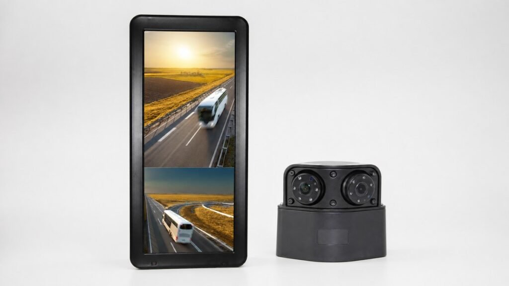
A side mirror camera monitor system combines exterior cameras with an in-cab display so the driver can view selected areas beside or behind a commercial vehicle. The purchasing challenge is not simply choosing a wide screen or a camera with the widest listed angle. The monitor, cameras, signal format, image direction, power design, connectors, cable routes, brackets, and driver-view layout must work as one approved configuration.
This distinction matters for distributors building a repeatable kit, fleets retrofitting different body types, and engineers preparing an OEM installation. A component can meet its own specification and still be wrong for the intended mounting position or wiring architecture.
This guide uses available Xinvisual product specifications to show how to prepare an RFQ and approve a sample. It does not establish that a camera monitor system may legally replace mandatory physical mirrors. Mirror requirements, homologation, approvals, and installation rules depend on the vehicle and operating jurisdiction and require a separate current review.
What Is a Side Mirror Camera Monitor System?
For procurement purposes, the system has four connected layers: exterior cameras, an in-cab monitor, the video and power harness, and the installed mounting geometry. The term describes an architecture, not a universal connector standard or legal classification. Approve the monitor, cameras, harness, settings, and mounting plan as one compatibility record.
Xinvisual’s mirror monitor category provides product-level display options. The purchasing document should go further by defining what each camera must show and how the complete installed sample will be accepted.
Application Scenarios
Trucks and Distribution Vehicles
A truck may use side cameras for low-speed maneuvering, turning, or observation beside the body. Define the target area before choosing a lens because cab width, body length, mounting height, and existing mirrors change the required view.
Buses and Coaches
Long vehicle bodies can make side observation important during terminal, curb, and depot movement. Assess a split display from the driver’s seated position, including glare, viewing distance, and the apparent size of relevant objects.
Construction and Agricultural Equipment
These vehicles may operate around attachments, articulated sections, or changing work zones. Place cameras around the actual equipment envelope and include cable movement, protection, and service access in the design.
Fleet Retrofit and OEM Integration
Retrofits must fit existing cab space, electrical architecture, and maintenance procedures. OEM programs also require controlled drawings and connector assignments. Approve the exact bill of materials rather than a general product family.
A Two-Camera Xinvisual Reference Configuration
The available workbooks list a 12.3-inch DVR mirror monitor and two camera options in dual-camera system sheets. The table below presents model-specific reference facts; it is not a claim that every combination is ready for every vehicle without sample testing.
| Component | Available Xinvisual Specifications | Purchasing Use |
|---|---|---|
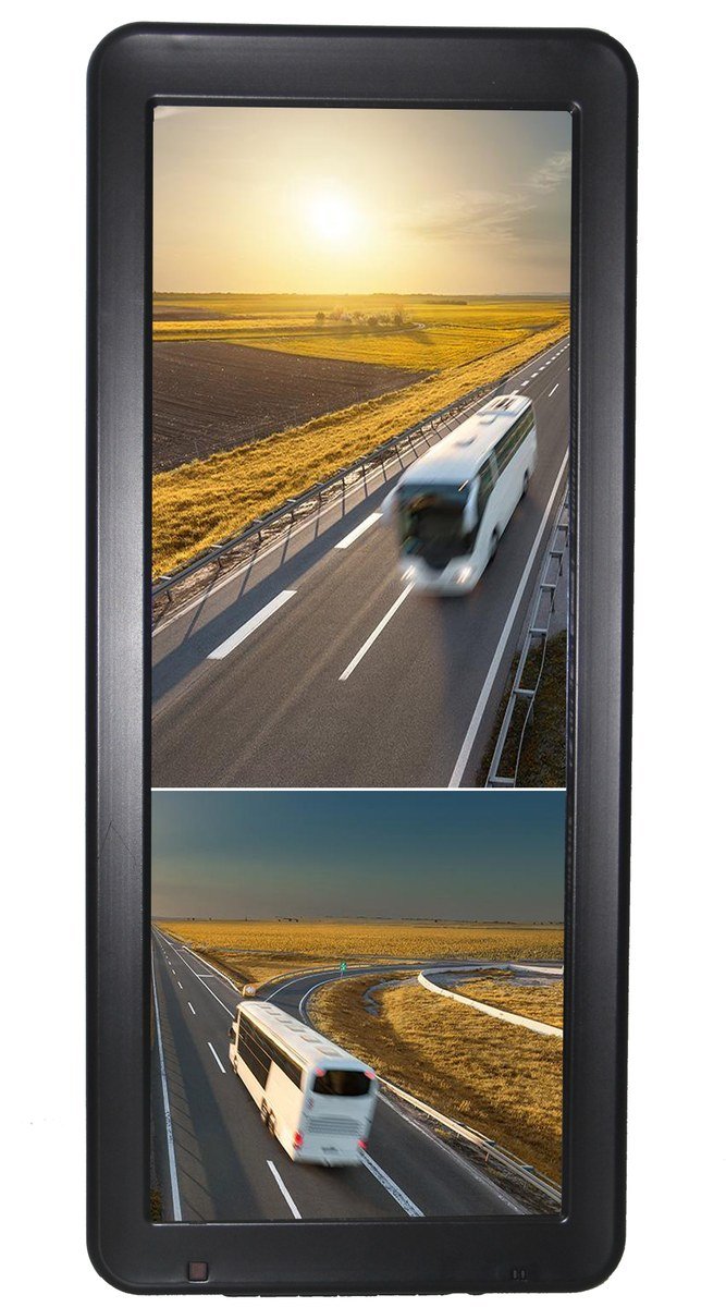
| 12.3-inch DVR mirror monitor | 12.3-inch 8:3 IPS display; 1920(H) x RGB x 720(V); 850 cd/m2 brightness; PAL/NTSC/Mix; DC12V-36V; two video inputs; CVBS, AHD720P, AHD960P, AHD1080P, and Mix support; mirror/normal adjustment by channel; TF recording up to 256GB | Dual side, side-and-rear, or other two-camera layouts where display and recording are required |
| Side camera option | AHD 1080; PAL/NTSC; PAL 1920 x 1080; IP69K; night vision; DC12V; 4-pin aviation plug; mirror/normal function; 130-, 90-, or 60-degree angle options | Camera option where the selected housing and angle fit the approved mounting position |
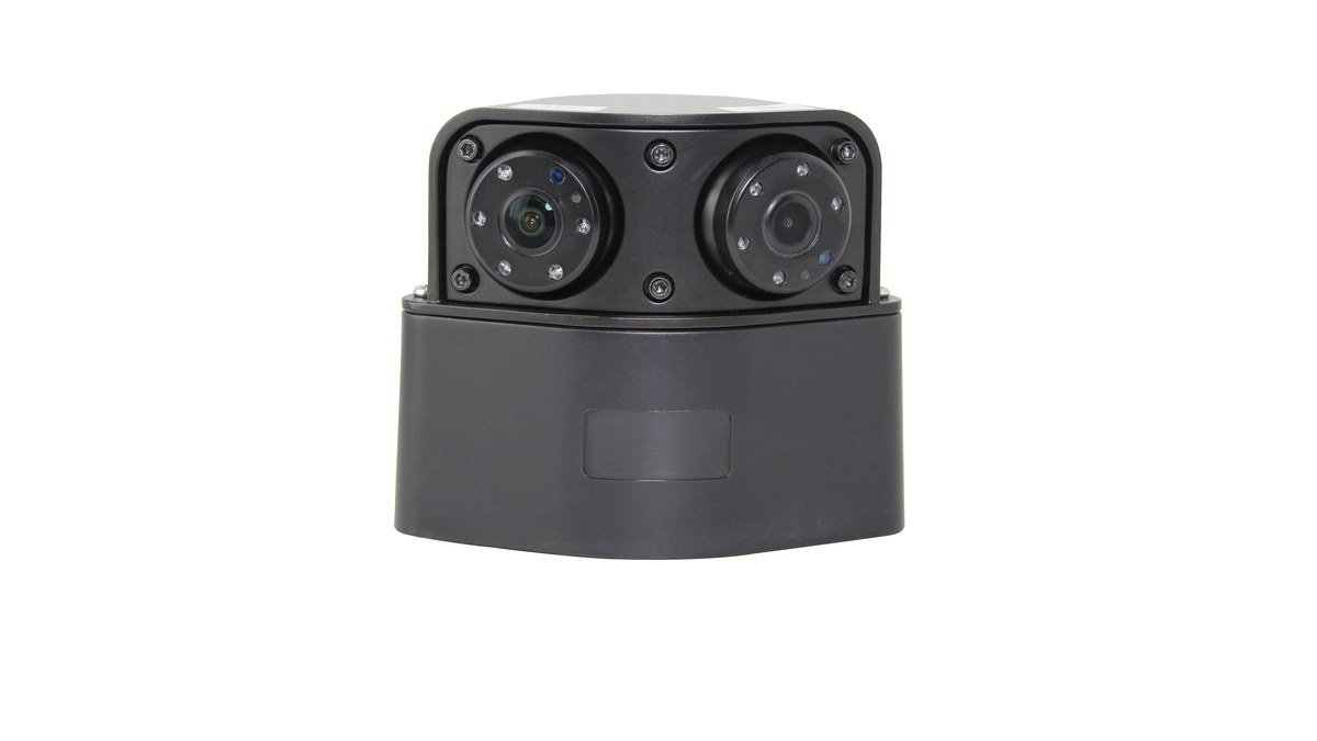
| Dual-lens camera option | AHD 1080; PAL/NTSC; PAL 1920 x 1080; IP69K; night vision; DC12V; 4-pin aviation plug; mirror/normal function; 150- or 90-degree angle options | Alternative housing and angle selection for the approved vehicle layout |
The monitor source also lists undervoltage, overvoltage, overload, short-circuit, and reverse-polarity protection. These are monitor fields only. They do not prove the same input range or protection behavior for the cameras.
Technical Solution: Make Seven Decisions Before Ordering
1. Decide Whether the System Supports or Replaces Existing Mirrors
Write the intended role in the RFQ. A supplemental system can add driver information while retaining required mirrors. Replacing a mandatory mirror creates a separate compliance and approval question that product descriptions, screen size, or resolution cannot answer.
2. Map the Required View Before Choosing the Camera Angle
Draw the vehicle from above and from the side. Mark target areas, possible mounts, body edges, moving equipment, and obstructions, then compare the available 130-, 90-, 60-, or 150-degree options by exact model. A wider angle can show more area but make distant objects appear smaller, so approve the installed image instead of selecting the largest number.
3. Match Resolution and Video Format as a System
The monitor lists CVBS, AHD720P, AHD960P, AHD1080P, and mixed input. Both camera examples list AHD 1080 and PAL/NTSC. Confirm compatibility by ordered model, signal setting, channel, and harness.
Connector appearance is not enough. A 4-pin plug does not by itself confirm the video format, pin assignment, power arrangement, or mating connector. Xinvisual’s AHD versus analog camera guide explains the signal distinction, while the RFQ should record the selected format for every channel.
4. Approve Split-Screen Layout and Image Direction
The monitor has two video inputs and supports mirror or normal adjustment by channel; the cameras also list mirror/normal functions. Decide where orientation will be controlled and avoid an undocumented double reversal. Test left and right references with recognizable markers and confirm that objects remain usable when two views share the 8:3 display. Stitched surround view, automatic object detection, and legal mirror-replacement layouts are not confirmed.
5. Separate Monitor Power from Camera Power
The monitor is listed for DC12V-36V input, while both cameras are DC12V. Do not apply the monitor’s range to the cameras. Document the camera power source, regulation, protection, ground, connector pins, and permitted load, then test the sample through representative vehicle operating states.
6. Control Connectors and Cable Routes
Both cameras list a 4-pin aviation plug. Confirm the mating pair and pin assignment before production. The vehicle camera connector guide structures checks for video, power, ground, sealing, strain relief, and serviceability. Measure routes through cab entry, body transitions, movement, heat, sharp edges, and service loops rather than selecting cable from vehicle length alone.
7. Define Recording and File Handling
The monitor lists TF recording up to 256GB, loop recording, automatic overwrite, important-file locking, online playback, and computer backup. Capacity does not establish a fixed duration, so measure retention in the approved configuration. Write viewing and evidence-retention requirements as separate acceptance items.
Product and System Selection Guidance
Use this sequence to narrow the configuration:
- Define the vehicle, body, operating task, and intended role of the system.
- Map each required view and candidate camera position.
- Select angle options only after estimating the installed field of view.
- Match monitor inputs, camera signal, resolution, PAL/NTSC setting, and image direction.
- Design monitor and camera power separately.
- Confirm mating connectors, pinout, extension cables, and mounting hardware.
- Decide whether recording is required and define file-handling expectations.
- Test one representative installation and freeze the approved bill of materials.
The 12.3-inch electronic smart mirror product page can support display-level evaluation, and the vehicle camera category can support camera comparison. Final compatibility should still be recorded by exact model and approved configuration.
Sample Approval Plan
Bench-test the proposed monitor, cameras, harness, and settings for stable video, image direction, channel identification, recording, playback, and export. Then install the system on a representative vehicle and record camera angles, visible area, obstructions, screen position, daytime and low-light image, cable support, connector retention, bracket stability, and service access. Different cab or body geometries may require separate approval samples.
Common Buyer Mistakes
Treating “Electronic Mirror” as Legal Replacement Approval
The product term describes the display format. It does not establish permission to remove required physical mirrors or confirm compliance in a market.
Choosing the Widest Camera Without an Installed View Test
Angle is only one part of field of view. Mounting height, lens direction, target distance, display size, and split-screen layout affect what the driver can use.
Assuming Every 4-Pin Aviation Connector Is Interchangeable
Similar housings can have different pin assignments or signal uses. Confirm both mating parts and the wiring diagram.
Applying DC12V-36V to the Whole System
That range belongs to the reference monitor. The listed cameras are DC12V, and their power plan must be confirmed separately.
Promising a Fixed Recording Time from Card Capacity
The monitor supports TF storage up to 256GB, but the reviewed information does not establish one universal retention period for every configuration.
Approving Components Without an Installed Bill of Materials
The approved system should include monitor, cameras, brackets, connector assignments, cable lengths, power design, settings, and installation records. Otherwise, repeat orders can drift from the tested sample.
Buyer Checklist
- Vehicle type, body, operating task, and target market recorded
- Supplemental-view or mirror-replacement role stated
- External approval requirements reviewed separately where applicable
- Required left, right, rear, or work-area views mapped
- Camera position and lens angle selected by installed geometry
- Monitor inputs and split-screen layout confirmed
- Resolution, video format, and PAL/NTSC setting matched
- Mirror/normal image setting approved for each channel
- Monitor input voltage and camera power checked separately
- Mating connectors and pin assignments documented
- Cable routes measured with service loops and movement included
- Brackets, fasteners, sealing, and strain relief included
- Recording capacity, playback, export, and overwrite behavior tested
- Daytime, low-light, and representative operating checks completed
- Approved photos, drawings, settings, and bill of materials retained
FAQ
Can a side mirror camera monitor system replace physical mirrors?
Do not assume so from a product name or hardware specification. Whether physical mirrors may be removed depends on the vehicle, market, and current approval requirements. Treat compliance as a separate documented review.
Is a 12.3-inch mirror monitor suitable for two side cameras?
The available 12.3-inch DVR mirror-monitor specifications list two video inputs and an 8:3 display, so they can support a two-camera configuration discussion. Buyers must still approve camera positions, split-screen readability, signal settings, image direction, wiring, and the installed view.
Does a 4-pin aviation plug guarantee camera and monitor compatibility?
No. Confirm the mating connector, pin assignment, video format, power, ground, and complete cable assembly. Physical appearance alone is not enough.
What should be included in a sample approval record?
Record exact models, camera locations and angles, monitor position, signal and image settings, power design, connectors, cable lengths, brackets, daytime and low-light findings, recording checks, photos, drawings, and the final bill of materials.
CTA
Send Xinvisual the vehicle and body type, required side and rear views, intended monitor position, recording requirement, power plan, connector preference, and measured cable routes.
Request a Configuration Review
The team can match available product specifications to a sample configuration and identify the items that still require installation or market-specific approval.