

A 360 surround view calibration handover needs more than four pictures on a monitor. The installer should verify each camera view, complete the exact system’s calibration procedure, check the stitched ground view against the manufacturer’s acceptance criteria, and show the driver the display’s limits before the fleet accepts the installation.
This checklist gives installers, distributors and fleet buyers a practical sequence: pre-checks, individual-view checks, calibration, static acceptance, a controlled maneuver test and a written handover record. It is a delivery checklist, not a replacement for the model-specific installation manual.
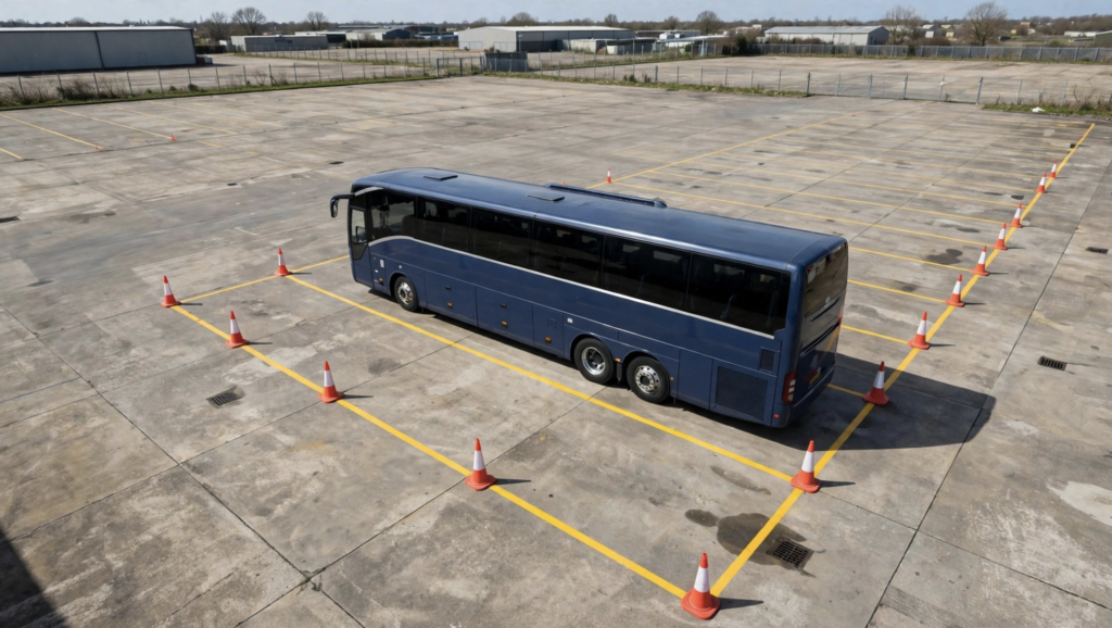
Cover image: AI-generated illustration of a coach in a depot yard with cones and painted lines. It does not show a Xinvisual installation or calibration test. The cones and yard markings are not a calibration pattern.
What Does Calibration Acceptance Actually Prove?
Installation checks establish that the specified equipment is mounted, connected and operating. Calibration checks establish that the cameras and stitched image are configured for the vehicle according to the system manual. Handover adds evidence that the agreed views and operating modes work and that the driver understands their limitations.
Separate ground alignment from tall-object appearance. A stitched bird’s-eye image is a processed view, not a direct overhead photograph or a distance-measuring instrument. An upright object may look stretched, shifted or partly absent near a join even when ground references align. Do not use a perfectly continuous tall cone as a universal pass criterion.
For example, Nissan’s official Around View Monitor guidance describes possible tall-object misalignment or omission at seams and differences between displayed and actual distances. That is an example of documented display limitations, not a specification for a Xinvisual system; the installed model’s manual controls its acceptance criteria.
Cameras support the driver’s observations. Keep the vehicle’s mirrors, direct checks and any site-required spotter procedure in use. A successful calibration does not certify that every hazard is visible.
Step 1: Prepare the Vehicle, Work Area and Documents
- Suitable calibration area: use the surface, clearances and lighting required by the system manual. Start with a level, unobstructed work area; avoid a ramp, uneven ground, glare or shadows that prevent reliable recognition of the specified references.
- Recorded vehicle configuration: confirm tire pressures and ride height according to the vehicle instructions. Record the load state and relevant body, door, tail-lift or trailer configuration. If an operating configuration changes camera geometry or coverage, agree how it will be checked rather than assuming one calibration covers every state.
- Clean lenses and visible references: remove contamination using the camera manufacturer’s cleaning instructions. Keep people and loose objects away from the reference area during image capture.
- Power and inputs: check the specified supply, connector seating, cable support and front/rear/left/right assignments. A visible image alone does not prove that the channel is assigned correctly.
- Correct documents: record the host, camera and monitor models, software version where available, and the revision of the installation manual. Obtain the correct calibration target or cloth and the matching procedure before starting.
If the required conditions or instructions are unavailable, resolve that gap before calibration. General wiring and mounting preparation is covered in our fleet camera installation guide; the 360° model manual takes precedence for camera placement and calibration.
Step 2: Check Every Camera Before Stitching
Review front, rear, left and right images individually. Stitching cannot recover a reference area that a camera cannot see.
| Check | What to verify | If it fails |
|---|---|---|
| Image present and stable | No unexplained loss, flicker or rolling picture during the required check. | Check supply, signal compatibility, connectors and channel assignment. |
| Correct view and orientation | Each channel shows the expected side, with the orientation required by the manual. | Correct the assignment, approved orientation setting or mounting as appropriate. |
| Required reference area visible | All required calibration points are visible; bodywork, brackets and cables do not obscure them. | Resolve the obstruction or camera position before stitching. Some vehicle body in a single view may be expected. |
| Usable image detail | The reference pattern is clear enough for the specified calibration method. | Check contamination, condensation, lighting and focus; investigate persistent blur. |
| Mount and cable support | The camera remains secure, and cables do not pull on it during normal vehicle operation. | Correct the mounting or cable support using the approved installation instructions. |
The Xinvisual 360° system operating instructions, section 5.4, describe checking the front and rear cloth views and the required black reference areas in both side views before panoramic stitching. This supports a useful checkpoint: verify the reference coverage first, then calibrate. Confirm that the manual and calibration materials match the system being fitted.
Step 3: Calibrate Using the Exact Model Procedure
Use the specified target type, layout, camera selection, measurement method and software settings. Measure the reference positions as instructed instead of estimating them. Keep the vehicle still during reference capture, confirm that all required points are visible, and follow the documented completion and saving sequence.
Record the target used and the configuration saved. Where the model supports a configuration backup, follow its documented method. Do not assume that calibration data from one vehicle can be copied to another: camera positions, body dimensions and configuration must be checked, and each installation still needs acceptance.
After a camera is moved, re-aimed or replaced, follow the manual’s recalibration requirements. A connector reseat that leaves camera geometry unchanged is not, by itself, a universal reason to recalibrate; verify signal stability and carry out the checks relevant to the repair.
If the documented procedure cannot be completed, pause and contact the system supplier. Do not label an unverified stitched view as calibrated.
Step 4: Check Ground Alignment and Demonstrate Display Limits
Secure the stationary vehicle under the site’s procedure before anyone enters the check area. Keep people clear during reference capture. Use the manufacturer’s prescribed references and acceptance method for ground alignment; ordinary yard lines or cones are supplementary checks, not substitutes for calibration targets.
- Ground references: inspect the specified ground features across front-left, front-right, rear-left and rear-right joins. Record any offset or distortion against the model’s criteria, rather than inventing a universal tolerance.
- Corners and coverage boundaries: identify visible ground, masked areas and any gaps required to be resolved. Check the areas relevant to the vehicle’s work, not only the easiest side to view.
- Upright-object demonstration: with the vehicle stationary, place a suitable marker at agreed positions around the seams. Compare individual and stitched views to demonstrate where its appearance changes. Treat this as a limitations briefing, not proof that every upright obstacle will be shown continuously.
- Cab visibility: check the monitor’s location and brightness from the driver’s normal position and under the lighting conditions included in the project acceptance plan.
Record pass, corrective action or retest for each required check, together with any documented display limitation. If the result cannot be explained against the manual, ask technical support to review it before acceptance.
Step 5: Run a Controlled Maneuver and Mode Check
Use a clear, controlled area, a competent driver and the site’s risk assessment. Clear everyone from the vehicle’s travel path before movement. Place any stationary reference objects while the vehicle is secured; do not ask an assistant to walk beside a moving vehicle to test a seam.
Where included in the agreed acceptance plan, check reversing, turning and relevant view selections. Observe image stability, unexplained freezing and mode behavior. Check any reverse or turn-triggered views only if those functions are specified for the installed configuration. Repeat the required checks after a normal restart, following the manual.
If loading or ride-height changes are relevant to the application, agree the configuration checks with the supplier and fleet. There is no model-independent requirement here to recalibrate every loaded vehicle. If a moving check reveals a problem, stop and investigate power, signal, mounting, configuration and display behavior; recalibration is not a remedy for every fault.
HSE’s safe maneuvering guidance places cameras within a wider approach to visibility and site safety. Keep the operating procedure and driver checks in place throughout acceptance.
Step 6: Brief the Driver and Complete the Handover Record
Demonstrate the installed system in the cab. Explain what each view shows, how to select it, where the seams and coverage limits are, and why the display cannot be used as a measurement tool. Show how to recognize a dirty, obstructed, frozen or otherwise unreliable view and who should receive a fault report. Do not dismiss an unexpected display as a training issue without checking it.
Keep a signed record with the installer and fleet, and provide the distributor with the agreed copy. This template contains record fields, not fabricated test results.
| Record item | What to enter |
|---|---|
| Vehicle and project | Fleet ID, vehicle type, body/trailer configuration, load state, ride height where relevant, date and location. |
| System fitted | Host, camera and monitor models; software version where available; camera positions and input assignments. |
| Calibration | Manual revision, target or cloth used, required measurements, completed procedure, saved settings and installer name. |
| Acceptance criteria and results | Manual/project criteria; individual views, ground references, corners, coverage limits, mode and maneuver checks; evidence references and retest results. |
| Driver briefing | Views and controls demonstrated, display limitations explained, fault-reporting contact and recipient’s acknowledgment. |
| Warranty | Xinvisual’s standard warranty period is one year. Record the applicable written coverage and exclusions; claim handling and replacement arrangements follow the agreed terms. |
| Open items | Issue, operational restriction where needed, responsible person and agreed follow-up date. Do not sign off an unresolved acceptance failure as passed. |
| Acceptance | Installer signature: __________ Fleet representative signature: __________ Date: __________ |
For school bus projects, the specification decisions that come before installation are covered in our school bus camera system buyer guide.
Quick Installer Sign-Off Checklist
- Correct manual, system models and vehicle configuration recorded.
- Work area, lenses, mounts, power and front/rear/left/right inputs checked.
- Required references visible in each camera before stitching.
- Calibration completed and settings saved using the documented procedure.
- All required seams, corners and ground references assessed against agreed criteria.
- Upright-object appearance and coverage limitations demonstrated.
- Specified maneuver, mode and restart checks completed.
- Driver briefing, instructions, contacts and open items recorded.
- Installer and fleet representative sign only for checks actually completed.
If Something Looks Wrong at Handover
| Observation | What to investigate | Next action |
|---|---|---|
| Ground references do not meet the specified seam criteria | Target placement, selected camera type, mounting geometry and saved configuration. | Check individual views and the procedure, correct the cause and repeat the required calibration and acceptance checks. |
| An upright marker changes shape or disappears near a join | Documented projection or seam limitations as well as camera coverage and calibration. | Compare individual views with the manual; document limitations and escalate unexplained behavior. |
| The image is stable while parked but fails during movement | Power or signal interruption, cable strain, loose mounting or other system faults. | Stop the test, diagnose the fault, then repeat the affected checks. Do not assume recalibration alone will fix it. |
| The driver reports an unexpected view | View selection, orientation, image quality, coverage and the driver’s understanding of the display. | Reproduce the concern safely, resolve any fault and explain verified limitations in the cab. |
Frequently Asked Questions
Can one calibration pattern be used for every 360° system?
No. Target type, placement, settings and acceptance criteria depend on the system. Use the instructions for the exact model and do not transfer measurements from a different kit.
Does moving a camera require another calibration?
A change in position or aim can affect the stitched image. Follow the model manual, complete the required recalibration and repeat the relevant acceptance checks. A repair that does not change camera geometry may require different checks.
Is a cone walkaround enough to accept the installation?
No. It can help demonstrate coverage and display limitations while the vehicle is stationary, but it does not replace the prescribed calibration references, individual-view checks or agreed operating tests.
Does a successful calibration replace mirrors or a spotter?
No. Continue direct observations, mirrors and the site’s required procedures, including a spotter where required. A camera system is a driver aid.
What should the distributor retain?
The vehicle and system configuration, manual revision, calibration record, acceptance results, briefing acknowledgment, warranty terms and unresolved items with clear ownership.
Discuss the Installation Before Ordering
Review our 360° surround view system and send the vehicle type and dimensions, planned camera locations, monitor requirements, body configuration and working environment. Ask which manual, calibration materials and acceptance procedure apply to the proposed configuration.
Contact Xinvisual to discuss your vehicle and handover requirements.