


Cover: AI-generated harbor scene illustration supplied with the manuscript; not a Xinvisual vessel installation or operating-procedure example.
A workboat camera system should be specified as a complete installation: cameras, connectors, mounts, cable routes, helm display, power and any recording equipment. Salt exposure, spray, engine vibration, changing loads and reflections off the water can affect different parts of that installation. Start with the crew’s tasks and the vessel’s working conditions, then evaluate the exact proposed configuration.
An IP rating alone does not establish salt-corrosion resistance or marine approval. Xinvisual manufactures commercial-vehicle cameras, monitors, wireless systems and MDVR products. Any proposed vessel use needs a model-specific review of the installation, supporting documents and project requirements. This guide gives marine equipment distributors, outfitters and operators a practical checklist for that review.
1. Map Camera Positions to Crew Tasks
Draw the vessel and mark each view the crew needs. Record who uses it and whether it must be visible live at the helm, recorded for later review, or both. Check the view with the normal cargo, deck equipment, rails and fenders in place.
| Position | Possible purpose | Checks at that position |
|---|---|---|
| Stern / aft deck | Berthing, stern-to work and deck activity | Spray and wash exposure, mounting structure, cable entry and view obstruction |
| Bow / forward deck | Quay or lock approaches, anchor and line handling | Crew movement, impact exposure and maintenance access |
| Port and starboard sides | Alongside work, fenders, gangways and transfer areas | Obstruction from rails, fenders, loads and deck equipment; reflected glare |
| Machinery space, where appropriate | Supplementary visual checks of a defined area | Equipment temperature limits, vibration, lighting, access and applicable space restrictions |
| Wheelhouse interior, where permitted | Recording a defined activity for incident review | Purpose, access permissions, retention policy and applicable privacy requirements |
Use the map to justify each view rather than copying a road-vehicle layout. A camera view is supplementary information: it does not replace the crew’s lookout, direct checks or required equipment. The IMO’s explanation of COLREG Rule 5 describes the continuing duty to maintain an appropriate lookout by sight, hearing and other available means.
2. Separate Ingress Protection, Corrosion and Marine Approval
These are three different checks. Ingress protection concerns what the enclosure rating covers under the stated test conditions. Corrosion assessment concerns the proposed materials, coatings, fasteners and exposure. Marine approval concerns the documentation required for the vessel, equipment function and project. Evidence for one does not automatically establish the others.
For example, IEC 60529 classifies enclosure protection, while IEC 60068-2-11 describes a salt-mist test method for assessing corrosion resistance. Referencing these standards does not mean a particular Xinvisual model has been tested to them; request the applicable report and its exact scope.
- Camera enclosure: confirm the exact rating, applicable standard and available test documentation for the proposed model.
- Connectors: confirm protection in the intended assembled condition, locking, cable entry and placement away from standing water. The camera’s rating does not automatically cover the harness.
- Materials: ask the installer and supplier to review brackets, fasteners, coatings and cables for the exposure and mounting structure, including interfaces between different materials.
- Access: plan a safe method for lens cleaning and inspection at the installed position. Do not rely on the crew reaching an inaccessible camera during operation.
- Project acceptance: confirm any flag, class, vessel-owner or operating-area requirements with the responsible parties before selecting equipment.
- Restricted spaces: do not assume a general vehicle camera is suitable for a space with special electrical, environmental or hazardous-area requirements.
Xinvisual lists selected IP69K vehicle-camera models. Review each model’s limits and evidence separately from any proposed vessel use. Our vehicle camera connector guide explains interface checks. The IP69K heavy-duty vehicle overview provides vehicle-use context; it is not evidence of marine suitability or a substitute for model-specific documentation.
3. Review Mounting and Cable Strain Relief
Specify the mounting position, adjustment method, fixing arrangement and cable support with the installer. Confirm that the assembly is suitable for the mounting surface and can retain its intended aim under the expected vibration and movement. Follow the applicable installation instructions rather than adding a universal tightening torque or locking method.
Arrange an early service re-check after the agreed initial operating period. Inspect aim, mount security, cable movement, connector condition and image stability. The interval should follow the equipment instructions and vessel maintenance plan; a first-week check can be agreed as an additional commissioning step, not a universal standard.
4. Test the Wheelhouse Monitor from the Helm
Evaluate the proposed display from the operator’s working position. A catalogue image or indoor bench demonstration does not establish readability in the wheelhouse.
- Can the operator see the display without obstructing the forward view, instruments or controls?
- Is the required scene visible with glare from windows or water at representative working hours, including low sun?
- Can the exact model be dimmed appropriately for the intended night operation? Check its actual controls and settings.
- Are the individual images in a split view large enough for their assigned tasks? Confirm image orientation and coverage; do not assume a video view provides a reliable distance measurement.
- Are the monitor’s mounting, environmental and electrical limits acceptable at the selected location?
5. Plan Wiring and Check Wireless Links in Place
Review cable routes before installation. Avoid likely standing water, bilges, moving machinery, pinch points and sharp edges where practicable. Have the qualified installer specify cable protection, support, service access and the method for each deck penetration or hatch crossing. Preserve the required integrity of the vessel’s structure and boundaries.
Label cables and connectors at both ends, and document the signal format and pinout. Confirm the proposed camera, monitor and recorder combination before connecting existing equipment; a connector that looks familiar is not enough to establish compatibility.
Where a wired run is impractical, a wireless link may be evaluated for a defined position. Test the exact camera and receiver at their proposed locations with normal hatches, equipment and cargo in place. Check continuity and delay during the intended task. An open-area range figure is not an installed-vessel guarantee. If the link is unreliable, review the arrangement or a wired alternative before approval.
6. Check Power for the Whole System
Record the vessel supply, intended power source for each device and relevant operating conditions, including starting and charging. Have the installer compare these with the documented requirements of the selected equipment and specify the distribution and protection arrangements.
Calculate demand for all cameras, monitor, recorder and accessories together. Confirm both total and per-output limits where a monitor or recorder supplies cameras. A device’s wide input-voltage range does not establish its camera-output voltage or available current. Use the exact model documentation rather than a product-family voltage statement.
7. Separate Live Views from Recording Requirements
Live video and recorded footage serve different tasks. List which views must be recorded, the recording schedule, retention target, who retrieves footage and whether remote access is needed. Confirm the following for the ordered recorder and its installation:
- Channels and compatibility: derive the recording-channel count from the camera map and any agreed expansion. Confirm the supported signals; see our 4-channel versus 8-channel MDVR guide.
- Recording settings: resolution, frame rate, bit rate, quality and operating schedule.
- Storage: supported media, usable capacity and expected retention. Use the MDVR storage calculation guide, then check retention with the actual settings.
- Retrieval: timestamps, playback, local export and file format; check that the intended reviewer can open the export.
- Options: confirm any cellular, Wi-Fi or positioning functions explicitly; do not assume they are included or that network coverage exists along the route.
- Installation: power, shutdown behavior, supported alarm inputs and environmental limits at the recorder location.
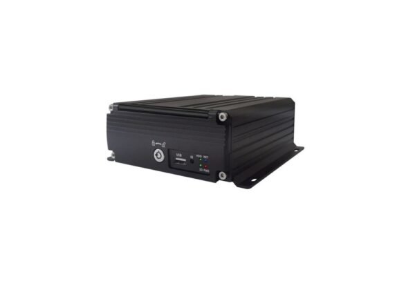
Do not assume every live camera is recorded, or that an MDVR includes a function because another version does. Sample playback and export checks are part of the configuration review.
8. Use a Written Procurement Checklist
- Vessel type, construction, operating area and applicable project requirements.
- Camera-position map with a named user and task for every view.
- Live-at-helm views separated from recorded-only views.
- Exact-model ingress evidence, corrosion information and any required approvals reviewed separately.
- Exterior connector condition, locking, sealing and drainage arrangement.
- Bracket and fixing suitability for exposure and the mounting structure.
- Cable routes, penetrations, support and access documented.
- Monitor position, glare and night readability evaluated at the helm.
- Power supply and total system demand checked against the selected components.
- Recorder channels, retention and export workflow verified.
- Warranty applicability to the intended vessel use confirmed in writing.
- Commissioning re-check and subsequent maintenance plan agreed.
- Service parts and replacement procedures identified.
9. Approve Samples in Three Stages
- Bench checks: use the exact cameras, monitor, recorder, cables and connectors. Verify model identifiers, power and signal compatibility, connector pinout and supported triggers. Record the settings and test playback and export.
- Controlled vessel evaluation: have the responsible crew and installer assess the installed configuration under an agreed safe procedure. Review coverage, glare, night readability, image stability, mount security, cable movement and any wireless link in representative conditions.
- Early service review: at the agreed interval, inspect aim, fixings, connectors, lens condition and recording operation. File photos, settings, results and the approved bill of materials with the service record.
A bench test can verify more than basic power-up, while a vessel trial reveals installation-specific issues. Neither test establishes long-term corrosion resistance or replaces required certification. Record unresolved items and repeat affected checks when the configuration changes.
Frequently Asked Questions
Does an IP rating prove a camera is suitable for a vessel?
No. An IP rating describes enclosure protection under specified conditions. It does not alone establish corrosion resistance, marine approval or the suitability of the connector, bracket and complete installation.
Can a vehicle monitor be considered for a wheelhouse?
It can be evaluated if its exact electrical, environmental and display characteristics meet the project requirements. Check glare, night dimming, mounting and any required documentation with the owner and qualified installer before selection.
Can wireless cameras be used on a workboat?
A wireless link may be considered for a defined position after testing the actual installation. Normal hatches, equipment, cargo and operating positions can affect the link. Do not treat open-area range as a performance guarantee.
How do I choose between four and eight recording channels?
Count the views that need recording, include agreed expansion and verify input compatibility. Review retention, wiring, power and the footage-review workflow at the same time. Vessel length alone does not determine the channel count.
Does Xinvisual provide marine-certified camera systems?
The products discussed here are commercial-vehicle products. This guide does not establish marine certification or class approval. Ask Xinvisual to review the exact proposed models and documents, and have the responsible project parties confirm acceptance for the vessel.
What warranty should be confirmed for vessel use?
Xinvisual’s standard warranty period is one year. Confirm in writing whether the intended vessel installation and exposure are covered, along with exclusions, claim procedure and freight responsibilities. Do not assume marine-use coverage from the warranty duration alone.
Request a Model-Specific Configuration Review
Send the vessel type, operating area, camera-position map, required live views, monitor location, supply voltage, exposure, recording and retention needs, and cable-route constraints. Include any approval or documentation requirements at the start. Contact Xinvisual to discuss the proposed configuration and evidence needed for your project.