

On a harvester or sprayer, camera placement should start with the task the operator needs to see: crop intake, an unloading outlet, a boom section or the area behind the machine. Map those tasks, select the views and verify them on the actual machine before the season. Camera count alone does not establish useful coverage.
This agricultural machinery camera system guide focuses on harvester and sprayer placement, installation checks and seasonal operation. For the broader introduction, see our wireless camera systems for agricultural equipment.
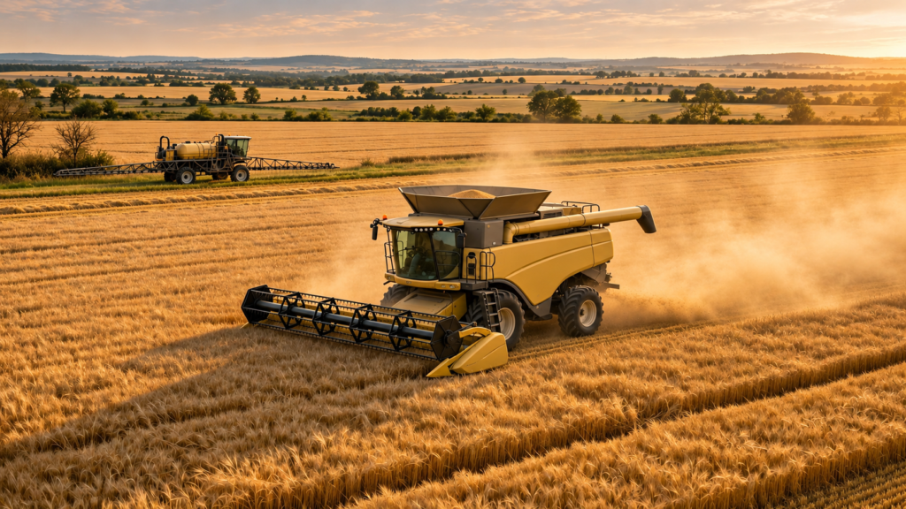
Cover image: AI-generated illustration of a combine and a parked sprayer in a field setting. It is not a Xinvisual installation, product test or recommended camera layout.
Start with a Camera Map, Not a Fixed Kit
A combine and a self-propelled sprayer have different working areas, attachments and movement. Before requesting a quotation, ask the operator which views are needed during field work, reversing, unloading, turning and transport. Check what the cab, mirrors and existing cameras already show.
- Define the task: identify the object or area that must be visible and the detail the operator needs to distinguish.
- Record the configuration: include the header or attachment, boom position, unloading arrangement and relevant trailer or receiving vehicle.
- Consider the environment: note dust, crop debris, spray products, washdown, vibration, low sun and any night operation.
- Plan the display: decide which view takes priority for each task, whether it is selected manually or by a verified trigger, and whether recording is required.
The camera map should name the mounting position, viewing task, monitor channel, cable or wireless route, power source and service access. A single view may cover more than one task if it shows enough detail; a difficult area may need more than one camera. Establish this through sample checks rather than a universal camera count.
Cameras supplement direct observation, mirrors and the farm’s operating procedures. They do not establish that every person, obstruction or moving part is visible.
Harvester Camera Placement: Header, Unloading and Rear Views
Visibility depends on the combine, header and cab layout. The following positions are candidates to assess, not mandatory mounting points for every machine.
| Candidate view | Task to define | Placement and acceptance checks |
|---|---|---|
| Header | Observe the relevant crop intake area, header edge or visible buildup. | Check the required working width and detail at the intended header heights and tilt positions. Keep the camera and cable clear of the reel, crop flow, guards and moving mechanisms. |
| Unloading outlet | Observe the outlet and its relationship to the receiving trailer or cart. | Test with the relevant receiving vehicle in an agreed safe setup. Check deployment and stowage of the auger and whether bodywork or crop dust obscures the view. |
| Rear | Support observations during reversing and yard or headland maneuvers. | Verify near-ground coverage as well as the required area farther back. A higher mount is not automatically better. Check the displayed orientation and any specified reverse-view switching. |
| Side or grain tank, if needed | Address a specific side-observation or tank-monitoring task. | Confirm the required detail, access for cleaning and a mounting position approved for the machine. Do not obstruct inspection access or guards. |
Assess image stability and contamination during a controlled operating trial. A clear image in the yard does not establish visibility in a harvest dust stream. Check the views through the expected header movement; after changing an attachment, bracket or camera aim, repeat the affected checks.
A camera may help an operator notice a problem, but it does not make blockage clearing safe while machinery is running. Before adjustments, cleaning or clearing a blockage, follow the machine’s isolation and securing instructions. The UK HSE’s agricultural machinery safe-use guidance explains Safe Stop and the need to secure machinery before intervention. Keep everyone clear of moving equipment during operating trials.
Sprayer Camera Placement: Boom Sections and Maneuvering Views
On a sprayer, identify which parts of the boom are difficult to observe from the normal operating position. Visibility changes with boom width, folding geometry, crop height and machine layout. Do not assume that the operator cannot see either tip, or that one fixed number of cameras suits all sprayers.
| Candidate view | Task to define | Placement and acceptance checks |
|---|---|---|
| Left and right boom sections | Observe an agreed tip, folding section or clearance area. | Assess each required area independently. Verify coverage in working and transport configurations; confirm that mounts and cables stay clear of joints, stops and folding mechanisms. |
| Boom or nozzle section | Visually inspect a specified section for an observable condition. | Agree the detail that must be visible. Video alone does not verify nozzle flow, application rate, distribution or correct spray performance; retain the machine’s specified checks. |
| Rear | Support reversing and headland observations. | Check the rear view with the boom in the configurations used for those tasks. Confirm any view-switching behavior for the exact system. |
| Front or road-travel area, if needed | Address an identified area not adequately visible by existing means. | Confirm the camera adds useful information and that the monitor does not obstruct the driver’s view or controls. |
Do not use a camera image as a substitute for an approved boom-clearance procedure or a specified obstacle-detection system. Plan any folding or movement test under the machine manufacturer’s instructions, with people outside the movement area.
Confirm Chemical Exposure and Washing Limits Separately
An ingress rating does not establish compatibility with the farm’s spray chemicals, detergents or cleaning routine. For example, ISO 20653 describes enclosure protection against foreign objects, access and water; its IP designation is not a general chemical-resistance specification.
Give the supplier the actual product names and available safety data sheets, contact conditions and washing routine. Ask for evidence applicable to the proposed camera, optical window, seals, cable jacket and connectors. Include exposure at folding sections and any connectors disconnected for service.
Obtain the cleaning and washing limits for the exact fitted components before approving the installation. Do not infer unrestricted pressure washing from a waterproof label or extend a camera enclosure rating to every cable joint. Our vehicle camera chemical-resistance checklist explains what to request when reviewing the complete assembly.
Choose Wired or Wireless Around the Actual Route
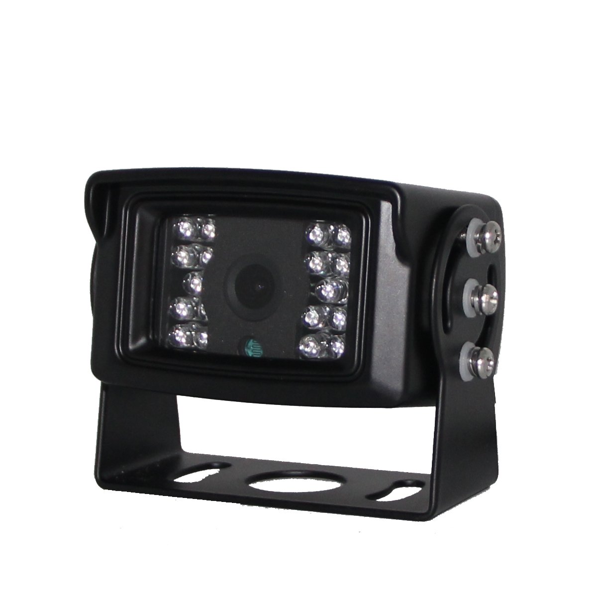
Long cable runs, folding sections and detachable implements can make a wireless link worth evaluating. A fixed, protected route may suit a wired system. Neither approach is automatically reliable or appropriate for a critical view simply because of its connection type.
For a wired installation, check cable length, signal compatibility, strain relief, bending requirements and clearance through the complete permitted movement of the boom or header. Avoid routing that can be pinched, abraded or caught during servicing.
For wireless, test the exact camera, receiver, antenna positions and number of operating channels on the machine. Check working and folded configurations and the relevant nearby equipment. Record any loss, delay, freezing or difficulty recognizing that an image is no longer current. A brochure’s open-area range is not a field-performance guarantee.
A wireless camera still needs power, whether through a verified vehicle feed or a supported battery arrangement. Confirm the supply range and current requirements separately for the camera, monitor, receiver and any recorder, together with the machine’s electrical requirements. Do not assume a voltage range for one component covers the full installation.
Use our wired versus wireless vehicle camera system guide for the broader comparison. Request a representative sample and an agreed test plan before committing to the fleet configuration.
Make the Monitor Part of the Placement Test
Review the image from the operator’s normal seated position. Test whether a split-screen view still shows the required detail, whether the priority view is easy to select and whether glare or low light affects readability during the intended work.
Agree a view-selection plan for harvesting, unloading, spraying and reversing. Verify automatic switching only where it is documented for the proposed configuration. Recording, simultaneous display and simultaneous recording channels are separate requirements; confirm each one in writing.
Use a Before, During and After-Season Routine
Before the season: prove the required views
Inspect mounts, lenses, cables and connectors using the approved maintenance instructions. Review each channel from the cab in its intended configuration, then run a controlled operating trial to assess vibration, dust, lighting and link behavior. Make physical adjustments only after safely stopping and securing the machine.
Record the agreed acceptance criteria and actual results. Include attachment changes, boom folding and unloading configurations where relevant. Resolve failed checks before signing off the installation; do not fill the record with assumed passes.
During the season: keep the views usable
Include an image and lens check in the pre-use routine, adjusting inspection frequency to contamination and the manufacturer’s instructions. Inspect after relevant chemical exposure or washing under the approved procedure. If a view degrades, record the channel, task and conditions—for example, a left-boom image that becomes cloudy after washing—so the cause can be investigated.
If a view is unavailable, follow the farm’s procedure for the affected operation. Do not proceed on the assumption that a powered monitor means a current, usable image.
After the season: retain the installation history
Inspect accessible mounts, wiring and connections as specified for storage. Record repeated soiling, fogging, movement or signal loss and investigate the cause. Repeated problems may involve placement, maintenance, component condition or several factors; they are not proof of one universal failure mode.
Where equipment also operates in cold conditions, our winter vehicle camera maintenance guide covers seasonal checks for salt, slush, low sun and frozen contamination.
Keep a Camera Map and Sample-Acceptance Record
Use the same record for the quotation, installation and pre-season review. The fields below are a template, not test results.
| Record item | What to include | Project entry |
|---|---|---|
| Machine and task | Machine type, attachments, operating configurations and the task served by each view. | ________________ |
| View and mounting | Position, required coverage and detail, mounting surface, service access and channel. | ________________ |
| System configuration | Exact cameras, monitor, cables or wireless components, power and any recording requirement. | ________________ |
| Exposure and care | Chemicals, washing limits, cleaning instructions and inspection/storage routine. | ________________ |
| Sample acceptance | Agreed criteria, tested configurations, actual results, unresolved items and corrective actions. | ________________ |
| Handover | Installer and operator acknowledgment, date, instructions supplied and support contact. | ________________ |
Frequently Asked Questions
Can the same camera kit serve a harvester and a sprayer?
Possibly, if the exact components and configuration meet both machines’ requirements. The mounting plan and acceptance checks still need to address different tasks, such as unloading on the harvester and boom-section observation on the sprayer.
How many cameras does a sprayer need?
There is no universal count. Map the areas that require a view, test the coverage and detail, and consider how many images the operator can use effectively. Separate boom-section views may be useful, but the machine layout determines whether they are needed.
Does IP69K establish resistance to spray chemicals?
No. Ask for evidence covering the actual chemical products, exposure conditions and complete proposed assembly. Washing limits and chemical compatibility must be confirmed separately.
What should a distributor send with the RFQ?
Send the camera map, machine and attachment details, relevant photographs or dimensions, required monitor views, recording needs, power information, exposure conditions and proposed acceptance checks. Ask the supplier to distinguish confirmed capabilities from items requiring sample validation.
Discuss a Configuration for Your Machine
Review Xinvisual’s wireless camera system range, then send us your harvester or sprayer requirements: machine type, planned header, unloading, boom or rear views, monitor needs, power information and working environment. Include spray products and the washing routine where applicable so the proposed configuration and any validation gaps can be reviewed before ordering.