

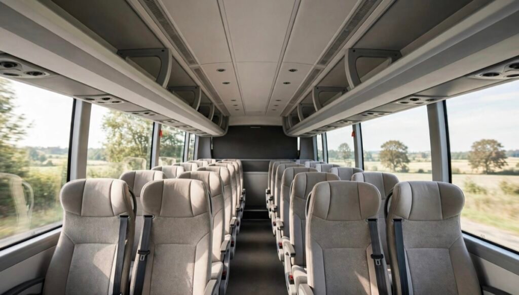
Cover: AI-generated coach cabin illustration; not a Xinvisual customer installation or product test.
Choosing a bus roof mounted monitor starts with two questions: how many screens does the vehicle need, and what size should they be? Start with the passenger seating plan, not a screen-size chart. The answer depends on which rows each screen must serve, the viewing angle from those seats, cabin obstructions and the content passengers need to read.
For fleet buyers, distributors and installers, the practical goal is to agree on a layout before ordering: define the viewing zones, compare candidate positions, then test the exact display from the least favorable seats in a representative vehicle.
Start with the Bus Seating Plan and Content
Before choosing a screen, collect information for the actual bus or coach:
- Vehicle body type and interior layout
- Seat rows, seats across each row and approximate seat pitch
- Ceiling height and possible mounting locations
- Luggage racks, vents, ceiling panels, hatches, grab rails and other obstructions
- Window positions and the lighting conditions passengers experience on normal routes
- Content type, such as entertainment video, route information or passenger messages
Content detail matters. Large video images and short messages may be easier to view from a distance than small text or subtitles, but the sample must prove that the intended content is readable from the required seats. Do not use a generic row-count or viewing-distance rule as a substitute for that test.
For general display-planning background, AVIXA’s display image size guidance distinguishes image size, content element size and viewer position. Use it as background for the viewing assessment, not as a bus installation approval or a substitute for cabin testing.
Define Passenger Viewing Zones Before Choosing Quantity
A viewing zone is the group of seats intended to use one screen. Mark the first and last rows in each zone on a seating plan, along with seats on both sides of the aisle. This makes the tradeoff visible: a longer zone may require fewer screens but can leave the farthest seats with a more distant or off-center view. Shorter zones may bring screens closer to passengers but require more hardware, cabling and mounting work.
Compare at least two practical layouts when the cabin is long or has unusual seating. For example, compare a single screen serving a longer zone with multiple screens positioned to serve shorter zones. Use the same content and cabin lighting when comparing layouts, and record which seats can read the material comfortably.
| Seat position to check | Why include it |
|---|---|
| First row served by the screen | It may be close to the display and view it at a steep angle |
| Last row served by the screen | It is often the farthest seat in that zone |
| Window-side seat | Window glare and off-center viewing may affect readability |
| Aisle-side seat | It may sit at a different horizontal angle from the screen |
| Seat affected by an obstruction | Racks, ceiling contours or other interior features can block part of the display |
These are sample positions to evaluate, not a fixed screen-to-seat ratio. The vehicle body, seat pitch, ceiling layout and content all affect the result.
Check Sightlines and Ceiling Conflicts
Layout problems can make an otherwise suitable display difficult to use:
- Excessive viewing distance — one front screen is asked to serve the full cabin, and subtitles or route details become unreadable at the back.
- Blocked sightlines — overhead luggage racks or ceiling curves clip part of the display for window-side passengers.
- Off-axis viewing — a seat may view the panel at a steep horizontal or vertical angle. A listed contrast-ratio viewing limit does not establish that small text remains readable.
- Ceiling conflicts — the planned mounting position clashes with ducting, a hatch, a grab rail or a roof structural member.
For example, a screen that looks acceptable on a workbench may leave rear passengers unable to read route information after installation. A proposed ceiling position may also prove unsuitable once the actual trim and obstructions are checked. Reviewing the drawing and testing a sample vehicle can identify these problems before a fleet order.
Compare Exact Monitor Specifications
Screen size is only one part of the comparison. Record the exact model and verify its diagonal size, resolution, brightness, contrast, viewing-angle notation, inputs, power requirement, housing dimensions and mounting style. Do not transfer a specification from one screen to another because the products look similar.
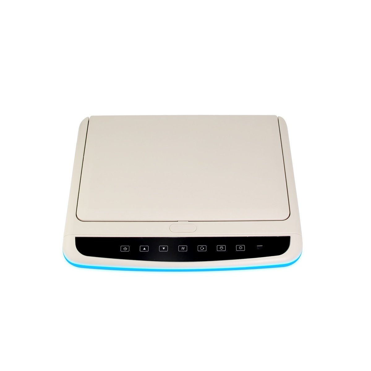
Android, DVD/MP5 playback, input interfaces, power requirements and control options vary by model. As one model-specific example, the current 19-inch roof-mounted monitor listing specifies 1440 × 900 resolution, 500 cd/m² brightness, 500:1 contrast and L/R/U/D viewing angles of 85°/85°/80°/80° at CR ≥ 10, with one video input. These listed values do not establish how far away content can be read or how many rows the display can serve. Confirm the ordered configuration and test it in the intended cabin.
See the 19-inch roof-mounted monitor for that model example and the roof-mounted monitor range for current product options. For an explanation of display-angle specifications and their conditions, review the vehicle monitor viewing-angle guide.
A wide listed viewing angle does not by itself prove that small text will be readable at the back of a coach. Judge the intended content from the passenger’s normal seated position.
Review Mounting, Clearance and Service Access
Review each proposed ceiling position with the installer and the vehicle owner before a sample is approved. Confirm that the selected bracket and attachment point are suitable for the exact monitor and vehicle. Check available headroom, opening or folding clearance if the model moves, cable routing, connector access and future service access.
Also check whether the screen or bracket could interfere with the driver’s view, passenger movement, controls or a required exit path. These details depend on the vehicle and installation; have the responsible vehicle professional assess the proposed position.
Take photos of the approved mounting point, screen angle and cable route. Keep them with the layout drawing so repeat installations across similar vehicles can follow the approved design.
Test the Layout in a Representative Vehicle
A powered screen on a workbench does not prove that passengers can use it in the installed position. Install a sample in a representative vehicle and test with the actual content or a realistic sample of it.
- Sit normally in the first and last row served by each screen
- Check seats on both sides of the aisle and any seat that is farther off-center
- Test small text or subtitles if passengers are expected to read them
- Check for reflections or glare under the cabin lighting conditions expected on the route
- Check whether racks, ceiling contours or other equipment block the display
- Review the screen position and clearance with the installer and vehicle operator
Record the result by seat position and photograph the approved view.
If the last row or an off-center seat cannot use the display as intended, compare a shorter zone, another mounting point, a different screen angle or an additional display. Retest the revised arrangement before confirming a fleet layout.
Avoid These Bus Monitor Layout Mistakes
Choosing the largest screen for every coach
A larger screen may be easier to see from some seats, but size alone does not solve distance, viewing angle, glare or a blocked sightline. Compare the screen in its intended position and content use.
Copying a layout from a different bus body
A layout from a tour coach may not fit a city bus, minibus or another coach with different seating and ceiling geometry. Recheck each body variant before repeating the installation.
Approving from a catalog photo
A product image does not show the passenger viewing positions in a specific vehicle. Approve the seating plan and installed sample together.
Leaving the media source until installation
Confirm the source device and required input before the ceiling is closed. The selected monitor’s inputs and control method vary by model and configuration.
Buyer Checklist Before Sample Approval
- Seating plan marked with seat rows and passenger positions
- Viewing zones defined for each screen
- Candidate screen positions checked against ceiling obstructions and service access
- Exact monitor model and specifications recorded
- Media source, video input and control method confirmed for that configuration
- Mounting style, bracket, opening clearance and cable route reviewed by the installer
- Driver sightline, passenger movement and exit paths checked on the target vehicle
- Sample tested from first, last, window-side and aisle-side seats in each zone
- Intended video, text or subtitle content checked in realistic cabin lighting
- Layout drawing, installation photos and approval record saved for repeat orders
Frequently Asked Questions
What size roof-mounted monitor is best for a bus?
There is no single best size for every bus. Begin with the seating zones, viewing positions and content requirements. Then shortlist exact models by screen size, resolution, brightness, viewing-angle conditions, inputs and mounting dimensions, and test the sample in the vehicle.
How many monitors does a bus need?
The seating plan and viewing test determine the number. Divide the cabin into zones, then check the farthest and most off-center seats served by each display. There is no universal screen-per-row rule that applies to every body layout.
Should the monitor be fixed or movable?
That depends on the exact model, cabin layout and intended use. Confirm whether the selected screen is fixed or movable, how it opens, what clearance it needs and whether it stays in the approved position. Test the chosen configuration on the actual vehicle.
Can the monitor work with our existing media source?
That depends on the selected monitor and media source. Confirm the required inputs, supported display formats and control method for the exact configuration before finalizing the wiring plan.
Discuss Your Bus Display Layout with Xinvisual
Share the vehicle type, seating plan, seat rows, proposed mounting points, ceiling obstructions, content type and preferred input or media source with Xinvisual Electronics. As a vehicle-display manufacturer, Xinvisual can review the project information and identify monitor specifications and installation details to confirm before sample approval.
Browse the roof-mounted monitor range, review the 19-inch monitor example, or send your bus display project requirements to Xinvisual Electronics. You can also email info@xinvisual.com.