

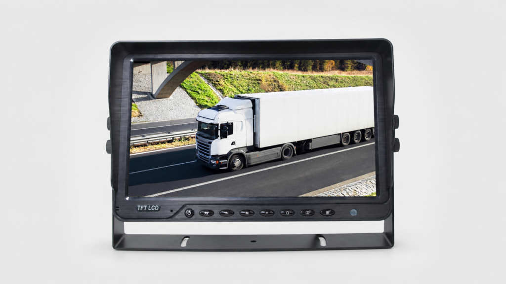
An HGV camera monitor system should be specified as an installed system, not as a monitor plus an unspecified set of cameras. For a heavy goods vehicle, the buyer needs to define which areas the driver must see, when each image should appear, whether footage must be recorded, and how the cameras, monitor, connectors, cables, and power supply will work together.
That process matters for fleet managers buying a standard kit, distributors building a repeatable product package, and engineers integrating hardware into a vehicle platform. A four-input monitor may be suitable for front, rear, left, and right views, but input count alone does not confirm camera compatibility, trigger behavior, recording, cable length, or installation acceptance.
This guide explains how to prepare an RFQ and sample test using available Xinvisual product specifications. It does not claim that a hardware configuration meets any national, city, fleet-association, permit, or insurance requirement. Those requirements must be checked separately for the vehicle, operating area, and current rules.
Start with the HGV Viewing Task
Rigid Distribution Trucks
A typical rigid truck may need a rear view for reversing, side views for low-speed maneuvering, and a forward or work-area view. The correct layout depends on body length, cab position, loading operation, and the driver's existing direct and mirror views. Record the intended purpose of each channel before choosing a camera.
Tractor-Trailer Combinations
An articulated vehicle adds a changing relationship between tractor and trailer. Cable routing, connection points, and service access deserve early attention. Buyers should identify whether the camera stays with the tractor or trailer, how the route crosses removable connections, and which parts of the installation will be disconnected during normal fleet operations.
Construction, Refuse, and Municipal Vehicles
These vehicles may have rear equipment, moving bodies, lifting mechanisms, or restricted work-area visibility. Define camera positions around the actual equipment envelope. A general road-vehicle diagram is not enough when a body, arm, hopper, or attachment changes the visible area.
Fleet Retrofit and OEM Integration
Retrofits must account for existing monitor space, electrical architecture, harness routes, and service practices. OEM projects also need a controlled bill of materials and change process. In both cases, the sample should represent the intended production configuration, including brackets and extension cables.
For a broader discussion of view placement, see Xinvisual's guide to combining rear, side, and front-view cameras. The HGV RFQ should then convert those views into exact component and wiring requirements.
An Available Four-Channel Configuration Example
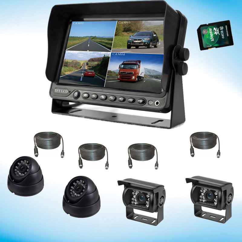
Available Xinvisual product specifications list a monitor, camera options, and extension cable lengths that can support a four-view system discussion. The following parameters are configuration examples, not a universal kit specification.
| Component Role | Intended Use | Available Xinvisual Configuration Example |
|---|---|---|
| Four-channel display | Multi-view display and automatic view switching | 7-inch screen; 1024 x RGB x 600 resolution; PAL/NTSC; DC10V-36V input; 5W power; four video inputs; four trigger wires; buttons and remote control |
| Rear camera | Rear-view option | PAL 1920 x 1080 pixels; 100-degree angle; IP69K; 4-pin plug; DC12V; mirror image without guide line; 18 IR LEDs |
| Side camera | Side-view option | PAL/NTSC; 1920 x 1080 pixels; 180-, 150-, or 120-degree lens options; IP69K; 4-pin plug; DC12V; mirror/normal image; six IR LEDs |
| Front camera | Forward-view option | PAL 1920 x 1080 pixels; 120-degree view angle; normal image; 4-pin plug; DC12V; IP69K |
The same source lists 3 m, 5 m, 10 m, 15 m, and 20 m extension cable items. It does not state that one fixed set of lengths fits every HGV. Cable selection must follow the measured route, connector positions, service loops, articulation points, and equipment movement.
There is also an important boundary around recording. The available four-channel display example confirms display inputs and trigger switching, but it does not confirm DVR recording. If incident recording, playback, file export, GPS, remote access, or storage capacity is required, add those as separate RFQ fields and evaluate a confirmed recording product. Buyers can compare the relevant MDVR product category without assuming that every multi-camera monitor records.
Technical Solution: Build the System from Five Decisions
1. Define Each Camera Position and Display Event
Create a channel table for front, rear, nearside, offside, interior, load area, or work equipment. For each channel, record whether it should display continuously, on driver selection, or after a vehicle signal activates a trigger input.
The available display example states that AV1 through AV4 have corresponding trigger wires and that an activated trigger switches the image to the corresponding camera. The source does not define the vehicle-side signal for every HGV, trigger priority when several signals are active, return timing, or custom logic. Confirm those behaviors on the sample and document the approved wiring.
2. Match Video Format and Image Direction
The monitor and camera must share a supported format. The reviewed monitor row lists PAL/NTSC, while the selected camera rows identify PAL or PAL/NTSC by model. Do not treat connector shape as proof of signal compatibility.
Image direction also depends on camera position. Available configuration examples include mirror-image, normal-image, and selectable mirror/normal camera options. Confirm the ordered setting and check what the driver actually sees after installation. A left or right view that appears reversed from the approved layout can create confusion even when the video is technically stable.
3. Separate Monitor Input Power from Camera Power
The available display example is listed for DC10V-36V input, while the camera examples are listed for DC12V. These are separate fields. The monitor's wide input range does not prove that any camera can accept the same vehicle supply, and the reviewed source does not state a camera-output voltage or load capacity.
The RFQ should identify how each camera receives power, the protection and fuse plan, grounding, and whether a monitor, control box, or separate regulated source supplies the cameras. Test starting, idling, normal driving, and accessory operation on the representative vehicle.
4. Specify Connectors and Measured Cable Routes
The selected camera rows list a 4-pin plug. Buyers still need the mating connector, pin assignment, cable type, and complete harness drawing. Use the vehicle camera connector guide to structure that check.
Measure the route from each mounting position to the monitor or control point. Include cab entry, body transitions, moving equipment, service access, bend protection, and strain relief. Choose extension lengths from the real route rather than vehicle length alone. For complete wired-system options, the wired vehicle camera system category is a useful internal reference.
5. Approve the Installed Sample
Bench testing confirms that the components power on and display video. Vehicle-level approval should also check the visible area, blind zones, image direction, trigger response, glare, low-light image, connector retention, cable movement, bracket stability, and access for maintenance.
Record the camera model and position, monitor model, cable lengths, connector map, wiring diagram, photos, settings, test conditions, findings, and final disposition. This record becomes especially valuable when a distributor or fleet needs repeat orders across several vehicle body types.
Product and System Selection Guidance
Choose the system in this order:
- List the required views and the event that should display each view.
- Decide whether the driver needs single-channel viewing, multi-view display, or both.
- Decide whether viewing is sufficient or recording is a separate requirement.
- Match video system, resolution, image direction, voltage, and connector pinout.
- Select camera housing and ingress protection for each mounting position.
- Measure every cable route and identify removable or moving connections.
- Define the sample test and acceptance record before the bulk order.
The vehicle monitor category and vehicle camera category can support component comparison. Final compatibility should be confirmed by exact model and approved configuration, not by category label.
Common Buyer Mistakes
Ordering Four Cameras Before Defining Four Views
The number of cameras should follow the visibility tasks. Camera position, viewing angle, and image direction may differ across front, rear, and side locations.
Assuming Four Inputs Mean Four-Channel Recording
Display inputs and DVR recording are different specifications. Confirm recording, storage, playback, export, and file protection separately when they are required.
Treating a 4-Pin Plug as a Compatibility Guarantee
Connectors that look similar can still differ in pin assignment or signal use. Confirm the complete mating pair and wiring diagram.
Applying the Monitor Voltage Range to the Cameras
The monitor and cameras can have different power requirements. In the reference configuration, the monitor input is DC10V-36V, while the listed cameras are DC12V.
Selecting Cable Length from the Vehicle Length
The installed route includes vertical movement, cab entry, equipment, bends, service loops, and connection points. Measure the route rather than estimating from the HGV's exterior dimensions.
Calling a Camera Kit a Compliance Package
A camera monitor system can support visibility, but this article does not establish compliance with any law, permit, fleet standard, or insurance rule. Obtain a current, jurisdiction-specific review when compliance is part of the purchase.
Component Checks and Replacement Decisions
Use the table below as a buyer troubleshooting guide before treating a symptom as product damage. Isolate the power, signal, cable, connector, camera, and monitor paths in a controlled sequence. Follow the vehicle manufacturer’s safety procedures, use qualified installers where required, and obtain engineering confirmation before changing wiring, mounting, or system architecture.
| Component | Buyer-observed symptom | Check first | When replacement may be necessary |
|---|---|---|---|
| Camera | No image, unstable image, fogging, or physical damage | Power, channel swap, cable, and connector | Camera fault remains after cable, power, and input checks |
| Monitor | No display, abnormal color, or one input unavailable | Power supply, input format, camera, and channel swap | Fault remains with a verified working camera and cable |
| Cable | Intermittent video, signal loss when moved, or visible abrasion | Connector seating, continuity, routing, and bending | Physical damage or continuity failure is confirmed |
| Connector | Corrosion, loose connection, or intermittent signal | Pin condition, locking, sealing, and cable termination | Pins, locking structure, or sealing cannot be restored |
A replacement decision should follow controlled checks rather than a single symptom. If the system is installed on a safety-critical vehicle, stop using the affected view until the fault has been assessed under the applicable operating and maintenance procedures.
Buyer Checklist
- HGV type, body type, and operating task recorded
- Required front, rear, side, interior, or work-area views mapped
- Display event defined for every camera channel
- Monitor input count and display mode confirmed
- Recording requirement separated from viewing requirement
- PAL/NTSC and other signal requirements matched by exact model
- Resolution and image direction confirmed for each camera
- Monitor input voltage and camera voltage checked separately
- Connector mating pair and pin assignment documented
- Cable routes measured and extension lengths listed
- Brackets, fasteners, cable support, and service access included
- Trigger source, priority, and return behavior tested
- Vehicle-level sample photos and findings saved
- Approved bill of materials and change control completed
- Any external compliance requirement reviewed separately
FAQ
How many cameras should an HGV camera monitor system use?
Use the number required by the vehicle's actual visibility tasks. A four-input monitor can support four camera channels, but the correct count and positions depend on the body, operation, driver workflow, and any separately reviewed requirements.
Does a four-channel HGV monitor automatically record all four cameras?
No. Input count does not confirm recording. The available display example confirms four video inputs and four trigger wires, but it does not confirm DVR recording. Specify recording and storage separately.
Can DC12V cameras connect directly to an HGV electrical system?
Do not assume this from vehicle type or monitor voltage. The selected cameras list DC12V, while the reference monitor lists DC10V-36V input. Confirm the camera power source, regulation, protection, grounding, and load plan.
What should be approved before a fleet-wide order?
Approve the exact camera positions, visible areas, monitor behavior, trigger logic, image direction, signal compatibility, power plan, connectors, cable lengths, brackets, recording requirement, and maintenance access on a representative vehicle. Save the approved bill of materials and installation record.
Request a Configuration Review
Need help confirming the right camera, monitor, cable, and connector combination for your vehicle?
Send us the vehicle type, camera positions, power voltage, cable length, video inputs, and recording requirements. We will help review the system configuration before sample approval.